Louder click pulse mod for Volca Kick

The Unit

The Volca Kick is a great Kick drum synthesizer, but I always been a bit dissapointed by the level of the pulse sound. Especially when turning the color knob left to for a softer pulse sound it is bareley noticable, by softer I mean when you turn the color knob left. During some invesitgation into the circuitry I was able to identify the circuitry responsible for the pulse sound and tweak its gain which really made the difference. But first I must warn you that I dont take any responsibility for any troubles that any modders may run into.
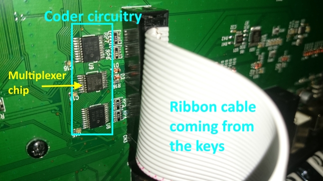
qcw.png

The Circuitry

The circuitry creating the pulse sound is a trigger pulse that is fed into some underdamped resonator circuitry where the color knob adjust the electrical mass property. After this the signal is fed into an inverting op-amp with a gain of 1, then into another summing mixer opamp where it is mixed with the resonator.

1920px-op-amp_schmitt_trigger.svg_

Some Theory.

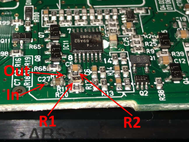
Changing the gain of the “unity gain” opamp as it has both the feed resistor R1 and feedback resistor R2 valued at 1 kOhm. The gain of this circuit is simply:

Gain = -R1/R2

I desoldered an ~525ohm smd resistor from some broken audio interface and soldered on top of R1,

The new R1 should then be:

R1 = 1/(1/1000ohm + 1/525ohm) = 344.3ohm using kirchoffs law.

The new gain will then be:

Gain = -1000/344.3 = -2.9   -This is how much the pulse sound wil be amplified!

The Mod

Warning: Do this modification at your own risk only.

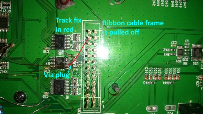
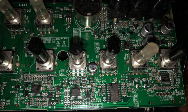
On the circuit board R1 is R11 and R2 is R12. look at R11. Be sure to use a grounded soldering iron when doing this mod, remember that doing this hack or mod is your own responsibility, and that it might break your device.

circuit dry.png

Here is a closer view with the 561 named resistor on top of the original resistor.

Untitle12d.png

Do note that this mod actually saturates the op-amp, especially at sharp clicks, but the difference is really notcieable anyway. Look in the following pictures from before and after click sound:

Conclusion.

After this mod I feel that the Volca Kick was more powerful in sound. I think before you only had the choice with short pulse and essentially only on or off with the volume knob. Now I can really hear the softer pulses very well and I think that it can really put some shape and punch into the sound. I think that putting a higher value at R2 could be a better choice than lowering R1 as it could introduce some interesting noise, but then you might have to change both R1 and R2 maybe into the 10-100kOhm region. I think that for anyone interested in experimenting with this mod may want to try to choose a gain around 3 or even 4 even if the op-amp clips (it does not clip as much with softer color pulse). At a gain of 2.9 im still able to have no pulse sound at all, you will start hear the pulse at 7-10 on level knob.Would be cool if anyone also could identify more about the circuitry too, (I know the opamp in the spotlight here is also has something to do with the envelope.)

More mods?

I was thinking about these mods:

  • Trigger input with Drive CV input for analog drum pads? Velocity mode..
  • Pitch CV input, LFO on pitch for earthquake kicks
  • CV input for Tone, decay, bend or time etc.?
  • Some kind of noise in click sound
  • Add resonance on rev.02 filter (Tone control)?
  • Increase voltage for “pulse” opamp for louder pulse? rails are now about +2V if im not wrong

Comments appreciated!

Here is the circuitry from ms20 used in V Kick, see any similarites from the circuit board posted under it? I see 6 missing diodes from the peak/resonance feedback, wonder what mode tweaks can be done. One thing I noticed while working on this mod was how sensitive the resonator circuit was (around the 13700 op-amp) it could reallu alter the sound just keeping my funigers close to it and this altered the sound to be more like an earth quake, maybe ill experiment more with this one day.

IMG_0878

Final


Volca Kick hack

Volca kick mod

volca kick pulse

Volca FM Midi without adding an extra plug!

Today we install a midi out feature without drilling into the Volca to add an extra midi plug, the midi out “hack points” will be connected to the unused 1 and 3 pin of the midi plug seen in the picture. These pins were soldered to ground however, so cutting the tracks on the circuit board was necessary. The two current limiting resistors are 220 Ohms. Note that the boards are quite dirty from soldering flux from the factory, the flux is not removed cause it actually protects the board.

Here are the cable schematics and a picture of the volca and the cable. I think this hack should work on the other volcas too! The only thing that is not transmitted is playing the keyboard directly, but it will send sequenced notes!

With Dexed you can upload sounds to your volca from a DAW/VST environment, but with midi out you can also send your sounds to the computer! you just enter the edit sound mode and then hit the export button, your beloved sound will then appear on your dexed VST.


Here are some High resolution pictures of the internals for those interested:

Volca Kick Teardown

A little handy synth device, posting some pictures in a slideshow. These devices are famous since they can be customized, they have a lot of “Hack points” to extend their usability!

The device is based upon an analog resonator (basically an low pass filter with a lot of resonance). It is digitally controlled which means the parameters can be altered from an external MIDI device. It also has a sequencer that can record knob movements! For even better photos without web compression, visit this dropbox folder:
https://www.dropbox.com/sh/083ifv9330wn9lx/AAAFm_M-hZTG89SoePqZ5qmJa?dl=0

As with the famous Roland 303, there is always some room for extra creativity by extending the usability of the device beyond its intended use. This video is a great example!

Big overhaul of an Chekoslovakian mill

During my summer job at STM Engineering, I have had alot of various work. The company specialises in CNC machining of components for the industry, but do have some manual machines too. It is often easier to use manual machines on small work that is not series production. The biggest manual machine in the factory was an 1996 Tos Kurim FGS 50/63 heavy duty mill from Chekoslovakia. These kind of machines is big, powerful and sturdy. Just like any other old stuff that is made to last for ages. However, the control unit had some problems, and I was up for the task to fix it.

2016-08-10 07.37.38.jpg

First problem with the machine was that the control voltage rails was shorted. I started tracing the short circuit, and ended up at a oil pressure switch on the hydraulic unit. In the image on the bottom left you can see the pressure switch itself. It can be adjusted to give a signal at a specific pressure level with a screw.

According to the manual, the pressure switch should be active at about 4 bars of pressure. I made a little tool to mount the thing to the air system in the workshop so I could test the unit. The thing was totally dead, and even at 7 bar’s of pressure there was no signal. However, pressing a pin into the inlet hole would give the signal. I also opened up the thing to see how it worked and I found that there was a hole in the diaphragm. And the reason for the short circuit in the system was that there was a hole too in the insulator plate, connecting the contact plate to the metal housing! Current would then enter the valve-block, wich is grounded.

The unit is quite simple in its workings, a diaphragm pushes a piston that pushes the contact plate. The insulator stop current going from the contact plate through the piston and into the stopper plate and then the main body. The stopper plate will stop the piston from breaking the contacts when the pressure is very high (60Bar+) Here is an view on how the thing works.

saml

Some new pressure sensors was found at RS Components at a fair price with fast delivery. However we needed to make an adapter since the threads was not the same, this was not difficult in a CNC Lathe. I used the same tool i made before to calibrate the units with air pressure.

The new sensors fixed the short circuit, but the mill was still not working. A big job was in front of me, cleaning all the contacts on the contactor relays! Yes, for some reason the contacts was very bad measuring with the multimeter. There are probably a thousand induvidual contact to be cleaned, but the CRC Contact Cleaner did the job very well!

In the next set of pictures you can see half of the contacts fromom only one row of relays, the other half of the contacts is inside the relays. Spraying and cleaning all the contacts with contact cleaner and q-tip gave good results. Some of the more worn and black contacts was polished on a rotating wheel.

Another issue was that some flyback arrester on six of the most used contactor coils was dead. They consisted of a resistor in series with a capacitor, connected in paralell with the contactor coil. I replaced the capacitors with a flyback diode instead, they do not age as capacitors tend to. The flyback arrester eliminates the reverse current coming from the coils when deactivated. The flyback current can wear out contacts, and interfere with sensitive electronics such as the digital readout.

This fix made the thing work atleast somewhat better than before, with the speed control for the spindle and the lights on the control panel woring. However there was still some problems, such as the electromagnetic valves locking in the engaged position. These electromagnetic valves is used to deliver oil pressure to the electromagnetic braking for the axes. I measured on the control-vaoltage rails, and between two points on the zero volt line I found that there was a difference of about 6 volts. This voltage would send a reverse current throug the electromagnetic valves and contactor coils. This is not enough to activate them, but enough to prevent them from returning from the activated position.

P7291533.JPG

After some hours troubleshooting, I found that a wire going to one of the relays was burned. I think the last person to install it did not torque the screw, heating the thing when current went through the bad contact. Fixing this totally changed everything, and now the mill works flawlessly! A funny fact that my boss told me was that four other experts had unsuccessfully tried to repair this machine!


Here are some other various pictures from the process, note the authentic blueprints!

This slideshow requires JavaScript.


And another slideshow from other things I have been working on this summer.

This slideshow requires JavaScript.

A smart little transistor tester

As I am in the process of rebuilding an DAC from the scratch, I figured out that I will match the components in its analog amplification stage. The analog stage consists of a i-v (current to voltage) converter, with a couple of classic NPN and PNP transistors. These components do vary alot when it comes to the amplification level, hFE / B. The result might be different amplitude on the two channels.

2016-04-13 20.08.07
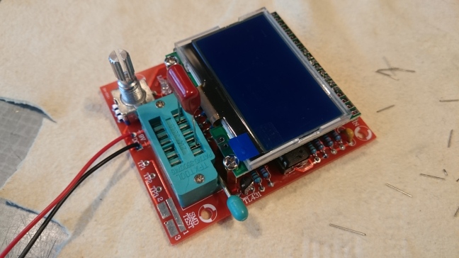
On Ebay I  found a little DIY device that could help me test theperformance of various transistors and other components. In the first picture you can see the finished unit, the blue-greenish slot is where the components is inserted. The device has tree test pins, and inserting a transistor in any way to these pins, it will identify the component and some parameters just by pressing the encoder button. It can also test capacitor ESR, diodes, zener-diodes, FET transistors, and so on. The accuracy is of course debartable, so I will test the transistors in other ways to verify.

2016-04-13 18.53.37This is all the parts that came in the packet. The circuit board tells you where each component is going, with the value or name of each part. The unit is based upon a Atmega328, just like the Arduino! After soldering, the board was cleaned with a solvent, I found that brake cleaner works quite well.

Here are some building pic’s, halfway in the process. I use a small screwdriver to make a smooth bend on the legs. I always double check the component, and sometimes even measure it to make shure it is the right one.

After the first powerup, the a self calibration test was run. This test includes shortening each leg, and then inserting a calibration capacitor wich is seen in the first picture. In the end I found that this is quite a clever unit, it could even find diodes inside transistors, and identify each leg! Even this is quite handy when designing prototype circuits, and even this justifies the price alone (24 USD) I also found the repeatability when testing transistor hFE quite satisfactory.

So next post will be about building a DAC!

Antique mechanical football game repair

IMG_9004

I found some pictures of an old mechanical football game I once repaired. The mechanisms are quite cool. The game works by coin insert, wich releases 10 steel balls into a elevator mechanism that hoist them one by one up to the hole in the middle of the game. The elevator is operated by a steel rod with a handle that the player will pull. The game works without electricity.

IMG_8995 asfd.jpg

This picture shows the inside workings of the machine (and a lot of random junk that was inside), the ball rail that puts the balls onto the lever mechanism has fallen off. I found that the rails were actually soldered, so the fix was done with just a soldering iron. As this thing was probably made by hand, quite a lot of adjustments was needed to get it to work in a acceptable way. The chains and bearings did get some good lubrication oil.

IMG_9002 asawe.jpg

The picture underneath shows the score mechanism, it needed some adjustments and oil to work in a good way. The rubber band was removed, probably put there by some other fixer that also left the junk inside the machine.

IMG_8998

Here is a slideshow for you with clean pictures!

This slideshow requires JavaScript.


Revolve NTNU, KA Aquilo 2013

Another year has passed, also a second car had to be built for our FS team. This year I was mainly working on developing a new upright and hub system for the suspension system. The experience from last year is invaluable in the new design. Our goal is to reduce the weight and the number of parts, this will be done by combining parts that previously were joined by bolts or welding. Pushing limits was iour goal for this year, and we was able to make a car that would outperform our 2012 car KA Borealis R easily. The new car KA Aquilo is seen here in a photoshoot together with a plane.

Aquilo-i-hangar

More photos of our new car, even more polish was used this year compared to last year! The bling is really impressive!

As said, my task for this year was to design the upright-hub system for the suspension. This is the parts that hold the wheel to the car. The first set of pictures shows the upright part alone. Siemens NX was used both for CAD design and FEM testing, the parts itself was CNC-machined by Devotek in Kongsberg.

The idea was to introduce an I-Beam design for both stiffness and lightweight.
As mentioned, we used alot of FEM analysis, we even tested each section of the part by itself. By doing so, it is easier to understand how each part will contribute to the total stiffness.

Another challenge we had this year was the welding of the frame. We used thinner and lighter tubes that were still within rules, but we could only have them in stainless steel quility. We also decided to TIG weld the frame ourselves, it was not an easy task due to the difficult material. I had been welding alot on last years car, and did also weld alot on this car. We had designed some fixture to make shure the frame was up to spec.

Another feature designed by the girl working in the engine group was some various length intake runners. The whole thing had to be inside the airbox, agin due to rules (there are alot of them) 3D printing was used for the aluminium intake runners and various other parts.

Some other pictures from the construction process. This year we built many more of the parts ourselves and very few of them broke, this is always a good thing!

This slideshow requires JavaScript.

This year we were also quite successful at Silverstone, clocking in at 16. position. We also won the price for most innovative electronic system with our CAN-bus system. The results we got is quite a acheivement considering all the 130 teams that participate. Many of them have been participating for many years!

This slideshow requires JavaScript.

A little update! with my upright design I won an iPod CAD design competition held by Siemens NX:

Upright calculations notes

Repair of machinery

IMG_9682

While working on the Revolve NTNU car in the workshop, we use alot of machinery. We had our own little workshop with a lathe and a mill. Unfortunatley our lathe is not of the best quality (China made)  The thing broke when the autofeed disengage did not engage. The result was that the thing broke a gear shaft for the main sled. It happened friday evening when the main workshop of the university was closed (and we had alot of machining to do). I had to get creative in making a gear shaft with a mill only to repair the broken lathe.

IMG_9653.JPG

If you have worked with machines you will probably laugh a bit. But the results was very good! The best thing about it was the nonstep variable speed control that is operated when running, and the fact that the machine was very stable. However I don not recommend doing this on a regular basis due to safety reasons. Here you can see a video of the thing in operation: Lathe video

Here you can see some pictures of the gear that broke off, the broken shaft and the new fabricated shaft.

Here are some various pictures of the build process of our new car! I am looking forward to se the end result.

This slideshow requires JavaScript.


Designing embedded computers course.

IMG_9207

This fall I took a course in “Embedded computers design”. The class is focused in making a complete pinball game machine system. The greenblue thing to the right is the game section, standing at the moment, at the left is all the control electronics. It has three nodes connected with a CAN and SPI bus. Two of the nodes is  some prefabricated evaluation boards. The last one we had to design ourselves using breadboards. Here you can see the breadboard at an early stage in the build process, with a serial interface chip and external RAM with a latch for addressing.

IMG_8989

More features was added thereafter. C code was used to program the whole system, and werial interface was used for debugging. Designing in a clean way makes it easier to debug the hardware. But even in doing so, we spent four hours debugging only to find that a two wire ribboncable was connected the wrong way! Here is the complete breadboard.

IMG_9025.JPG

The second node (the white NTNU board), is used for controlling the game and has alot of features such as capacitive faders. However we added the bigger joystick seen in the first pic as an extra feature to impress the teacher! It also made it easier to play the game. The NTNU board communicate via CAN bus.

IMG_9211

A slideshow of the various parts of the game:

This slideshow requires JavaScript.


Novation Midi keyboard repair


front.png

This Novation Remote 49 sl Compact keyboard had some keys that periodically were defective. These kind of errors are the worst thing to track down. Cause when you measure with the multimeter to find the bad connection, the little error deamon inside will passivate, and you will not find the faulty part.The unit has two circuit boards, one main board and one at the keys.

2016-02-21 17.41.24 edit

The first thing I suspected was some not so good looking solder joints on some diodes on the auxillary circuit board (see second picture). After this fix the keyboard worked for awhile and I was happy. However some weeks later the fault was back. I then went over the solderings on the coder circuits for the keys. This circuit converts the paralell input of the keys into a serial  signal to the microprocessor in the keyboard that writes the MIDI signals. Again, the keyboard worked for some weeks until the deamon was back. Once again I opened the thing, and just by checking the flat ribbon cable that connects the two circuit boards inside it went back into fully functional operation. I changed the cable, but the fault was back again after some time. Pretty annoyed by this deamon, I then went over every solder connection in the circuits between the coders and the keys. However the fault always came back. The next step was to change the actual components, and my attention fell to this multiplexer chip that was handeling the data coming from the ribbon cable and the keys.

2015-12-16 02.16.18 edi.jpg

Looking at the datasheet of this multiplexer, the chip had an “chip enable pin” that was supposed to be kept low for the chip to function. Measuring the circuits on the keyboard, the designers had forgotten to connect the chip to ground! Unless the chip has an puilldown resistor inside, the pin will then be “floating”. A floating pin is higly sensitive to electrical nois, and will go high or low depending on the direction of the wind.

chip enable

I finally thought I had managed to fix the problem, cause it worked for a long time after soldering this pin to ground. However this was not the case, I thought that the chip was broken, but replacing it would not fix the problem. I then made a lot of mess by replacing and resoldering various resistors and diodes to see if that fixed the problem. The result was quite messy, as the tracks circuit boards tend to loosen from the heat. After many hours of unsuccessful attempts, I wanted to throw the thing out the window and never see it again. But I decided reverse engineer the circuits (service manuals not available), and finding where the traces on the circuitboards would go. I inspected the circuits and found that from the multiplexer chip, 7 out of 8 of the inputs went into the ribbon cable to the keys. The last one went into a “via” on the circuit board throug a track inside the multilayer board.

Untitled.png


The problem was that I could not find the “other end” by measuring with the multimeter due to the fact that the trace was faulty. Probably the current of the “beep tester” was too big for the partly fauled trace to handle. However I did not know about the faulty trace, I was just looking hopelessly for the other end with the multimeter! But I also found an pin on the ribbon conector that apparently was lonely. Looking on a pin coniguration inscription on the auxillary board, it wasnt just a NC (not connected) pin.

2016-02-21 18.02.06

The last fix that killed the faulty deamon was a wire fix on the circuit board. I was quite supprised to find that the tracks on the circuit board itself were broken. That is the last thing I would suspect in the first place. The last picture shows the fix in red, the end result was alot cleaner than this hopeless mess.

2016-02-21 22.09.18 ed

At last, this keyboard learned a me a valuable lesson. That is to also look where you don’t really suspect you will find the fault. I am now quite happy that I did not throw the unit away, this board has alot of weight in the keys wich the newer ones dont have. They always find new ways to save more money.