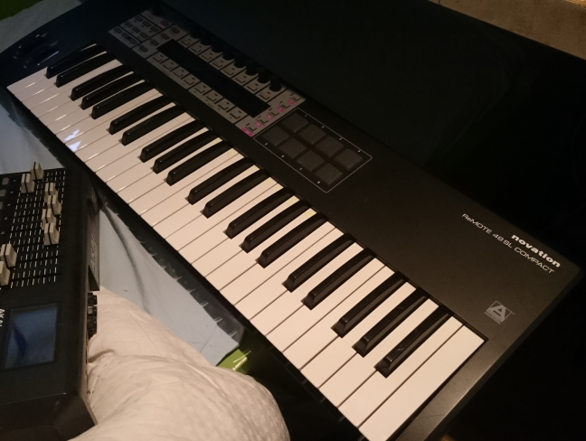
This Novation Remote 49 sl Compact keyboard had some keys that periodically were defective. These kind of errors are the worst thing to track down. Cause when you measure with the multimeter to find the bad connection, the little error deamon inside will passivate, and you will not find the faulty part.The unit has two circuit boards, one main board and one at the keys.
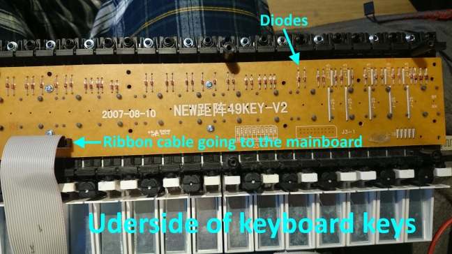
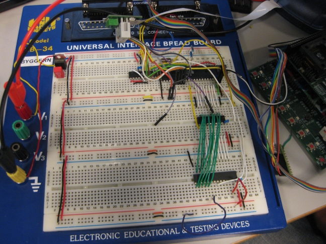
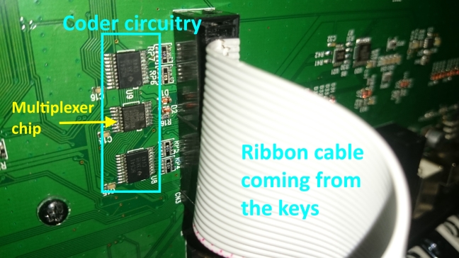
The first thing I suspected was some not so good looking solder joints on some diodes on the auxillary circuit board (see second picture). After this fix the keyboard worked for awhile and I was happy. However some weeks later the fault was back. I then went over the solderings on the coder circuits for the keys. This circuit converts the paralell input of the keys into a serial signal to the microprocessor in the keyboard that writes the MIDI signals. Again, the keyboard worked for some weeks until the deamon was back. Once again I opened the thing, and just by checking the flat ribbon cable that connects the two circuit boards inside it went back into fully functional operation. I changed the cable, but the fault was back again after some time. Pretty annoyed by this deamon, I then went over every solder connection in the circuits between the coders and the keys. However the fault always came back. The next step was to change the actual components, and my attention fell to this multiplexer chip that was handeling the data coming from the ribbon cable and the keys.
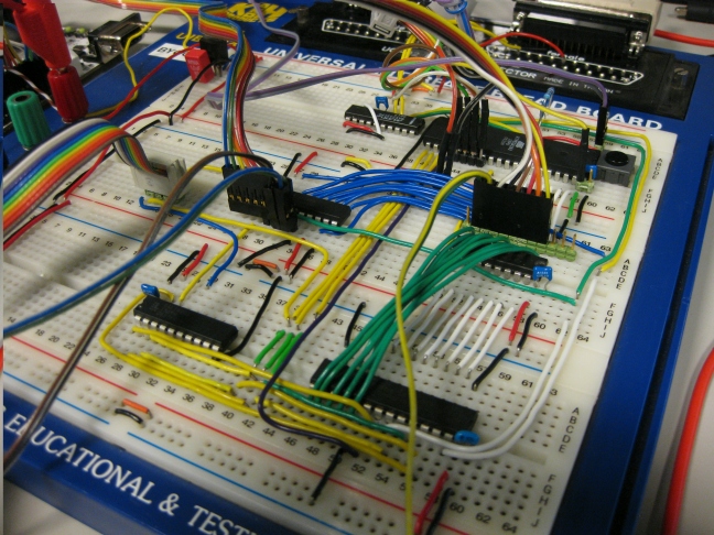
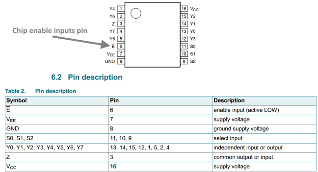
Looking at the datasheet of this multiplexer, the chip had an “chip enable pin” that was supposed to be kept low for the chip to function. Measuring the circuits on the keyboard, the designers had forgotten to connect the chip to ground! Unless the chip has an puilldown resistor inside, the pin will then be “floating”. A floating pin is higly sensitive to electrical nois, and will go high or low depending on the direction of the wind.
I finally thought I had managed to fix the problem, cause it worked for a long time after soldering this pin to ground. However this was not the case, I thought that the chip was broken, but replacing it would not fix the problem. I then made a lot of mess by replacing and resoldering various resistors and diodes to see if that fixed the problem. The result was quite messy, as the tracks circuit boards tend to loosen from the heat. After many hours of unsuccessful attempts, I wanted to throw the thing out the window and never see it again. But I decided reverse engineer the circuits (service manuals not available), and finding where the traces on the circuitboards would go. I inspected the circuits and found that from the multiplexer chip, 7 out of 8 of the inputs went into the ribbon cable to the keys. The last one went into a “via” on the circuit board throug a track inside the multilayer board.
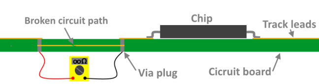
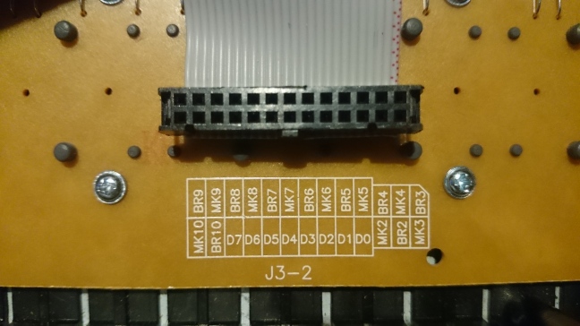
The problem was that I could not find the “other end” by measuring with the multimeter due to the fact that the trace was faulty. Probably the current of the “beep tester” was too big for the partly fauled trace to handle. However I did not know about the faulty trace, I was just looking hopelessly for the other end with the multimeter! But I also found an pin on the ribbon conector that apparently was lonely. Looking on a pin coniguration inscription on the auxillary board, it wasnt just a NC (not connected) pin.
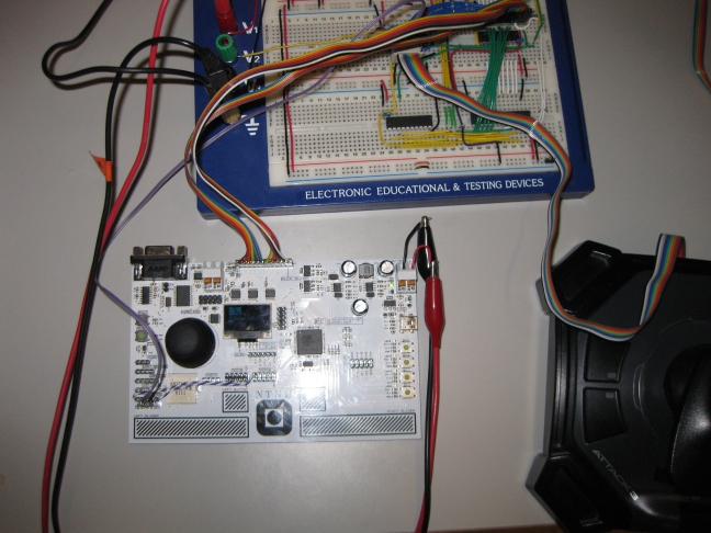
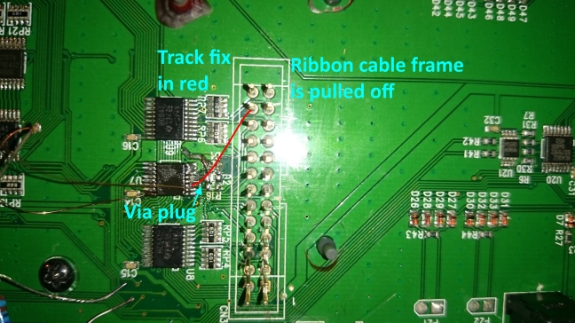
The last fix that killed the faulty deamon was a wire fix on the circuit board. I was quite supprised to find that the tracks on the circuit board itself were broken. That is the last thing I would suspect in the first place. The last picture shows the fix in red, the end result was alot cleaner than this hopeless mess.
At last, this keyboard learned a me a valuable lesson. That is to also look where you don’t really suspect you will find the fault. I am now quite happy that I did not throw the unit away, this board has alot of weight in the keys wich the newer ones dont have. They always find new ways to save more money.